 |
| Danger! Acid Moose on the loose! |
The Synth
Roland TB-303 must be one of the most fascinating piece of music gear of all time. I have never owned or played one but have loved the distinctive sound that has defined the whole acid techno music genre. About two years ago I was looking for interesting synth DIY-projects and found out about
Oakley Sound and their TM3030 clone. It's an accurate but modernised version of the original TB-303. It can be built with the original Japanese semiconductors or with more modern and easily sourced components. It doesn't have a sequencer like the original box has but has a special midi interface that reproduces many of the TB-303 features.
The Box
For some reason I have been hauling an old Macintosh Plus external hard drive enclosure with me for two decades. It's so beautiful in all it's dull greyness and brings back memories from the countless hours spent in front of our first computer back in early nineties. This must have cost a fortune in the eighties!
About 15 years ago I started thinking that it would be perfect enclosure for a DIY synth but somehow none of the projects I have done so far have felt fine enough for this unique box. I always ended up saving this one for later and used some other enclosure.
The Ultimate Acid Box
I decided to build a TM3030 and pretty soon got the idea of building two of them in the same box. It was immediately clear that this project would be special enough to finally utilize my dear hard drive enclosure! I originally thought about adding a DJ-mixer-style crossfader to mix the signal from the two TM3030's but decided to skip that as it would have been mechanically difficult to cut the enclosure without proper tools.
 |
| I'm pretty sure they designed this harddrive enclosure to have a second life as a synthesizer. I was able to fit 2 audio outputs, midi input and power connector directly in to the holes of the original connectors! |
 |
| Reused connector holes. |
Sourcing the Components
As I'm not a hardcore 303 fanatic I didn't care how authentic the component choices were. I mostly went with the modern components suggested in the TM3030 build instructions. Most of the parts were ordered from Reichelt but some were from suspicious asian ebay sellers. (It later turned out that it was a bad idea...)
Soldering, Soldering, Soldering...
It took well over a year to get this thing built. It really isn't that big but I just didn't have time to build anything. I decided to build both units at once because it's somewhat faster that way. On the other hand it decreased my build motivation because it took significantly longer to see any results.
 |
| Resistors first. |
 |
| Then some capacitors. |
 |
| ...and more capacitors! And ic:s and transistors... |
 |
| And wires! This is the most annoying part of the soldering. |
 |
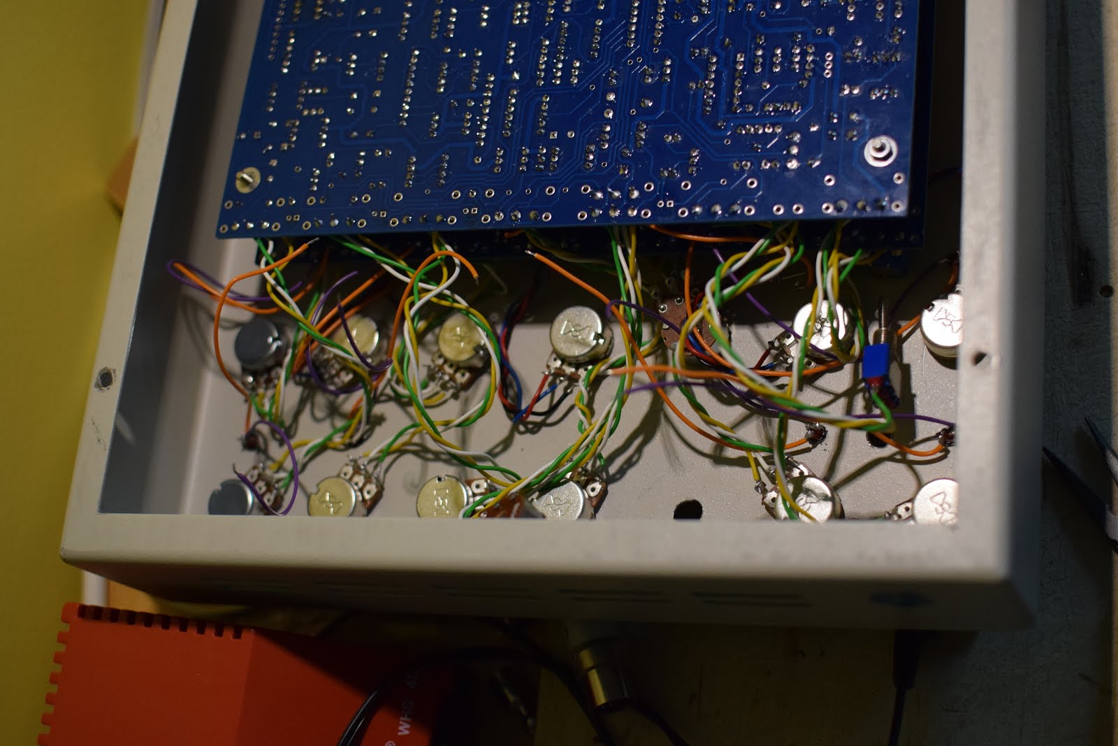
| Pots and switches in place. Pretty much ready to turn on the power. |
Debugging
After powering up the first unit for the first time it kind of worked but felt like the gate signal was inverted. Synth played a note when key was released and stopped when key was pressed down. The second unit behaved exactly the same.
After lots of debugging it turned out that the CA3080 OTA IC used in the VCA was bad. I had ordered these super cheap chips from ebay and apparently they were fake. I got new ones from
Partco and both units started working correctly. Tony from Oakley Sound provided excellent support at
Oakley Sound Systems Muff Wiggler forum. Thank you very much Tony!
The good thing about this CA3080 problem was that I spent lots of time studying the schematics and really learned to appreciate the unique envelope generation circuitry that contributes greatly to the 303 sound.
I also had one bad trimmer potentiometer that didn't change the resistance at all and also forgot to solder some pins from an IC in the second unit but other than that this relatively large soldering project went pretty well.
 |
| Trying to figure out what's happening with the VCA envelope. |
The Enclosure Nightmare
Everything looked good at the beginning. I was able to install all connectors directly to existing holes in the backside of the box. After that things got a lot more painful. An ideal DIY enclosure opens directly up so that it's easy to access the guts of the device. Unfortunately this enclosure consists of a big upper part and smaller back/bottom plate that slides inside the upper part. It meant long wires inside the box so that the enclosure parts could slide far enough to open the enclosure. I originally planned to attach pcb:s to the bottom plate and pots to the top plate but that would have meant extra long cables for every single led, pot and switch. I changed the plan and attached pcb:s to the upper half of the enclosure so that extra long cabling was required only for the back panel connectors. Unfortunately this meant that accessing the pcb:s would be difficult. I also had to drill some extra holes into the front panel for the pcb screws.
 |
| Planning the front panel layout. |
 |
| Mockup. I had to place everything in the front section because the pcb:s take rest of the space inside. |
Crappy Tools, Crappy Result
I have decent tools for electronics. I'm able to do consistent solder joints and if something doesn't work as expected I have enough measurement equipment to debug things. Unfortunately every DIY project also has the mechanical aspect. Some kind of front panel or enclosure is required and usually it means drilling holes, cutting metal, filing etc. I don't have proper work space or machinery for that kind of heavier work so it's always major headache for me. This project was no exception and the enclosure turned out to be made out of really heavy duty metal.
 |
| Ugly holes almost where I wanted them to be. Razor-sharp metal chips all over the garage. Ouch! |
 |
| Did I use a drill or a rifle? It took hours to smooth out those edges. |
Assembly
More Debugging: Cross Talk and Grounding Issues.
I finally got both units nicely into the the enclosure and started playing with the synth. At first everything seemed to be fine but then I realized both units were clearly audible on both outputs. This was a serious problem especially when adding high gain effects like distortion to one of the channels.
The first thing to check was of course grounding. After some measuring I realized the enclosure is not grounded at all. I had assumed that the big pads on the PCB connection points were connected to ground but it turned out they aren't. I also happened to use insulated audio connectors so there was no ground connection. I had to explicitly connect a thick ground wire from both PCB:s to the chassis.
After adding the ground connection I ran into another interesting problem. One of the units didn't start up at all and with some more measuring I noticed that one of the led holders was broken and +5V was bleeding to the enclosure. That effectively short circuited the power supply of the other unit. Luckily I noticed it before anything burned.
Grounding helped the cross talk issue but didn't cure it completely. The next step was to replace the thin wires going from pcb:s to audio output connectors with heavier and better shielded coaxial cabling. After that everything was working properly and I could smash one of the outputs with extreme high gain distortion without hearing any bleeding from the other unit.
 |
| Changed audio output connector cables to coaxial cables and got rid of cross talk issues. The sliding enclosure mechanism requires really long cables for the back panel connectors. |
The Result?
This is easily the best sounding thing I have ever built! It's simple and limited but so full of character! It's pretty much impossible to get bad sound out from it! It was definitely worth all the effort and I'm really satisfied with the result. The enclosure works nicely, looks good and is really heavy duty. (I hope I don't need to open it ever again...)
The next step is of course to learn to make some music with it. It requires careful sequencing to utilize all the features of the box. My Korg SQ-1 sequencer doesn't work very well with this because it doesn't generate slides or accents properly so I have been using my laptop and Ableton Live. I'm already toying with the idea of a custom hardware step sequencer to drive this beast.
Here's a video to demonstrate the sound:
https://www.youtube.com/watch?v=pwPW4uGKvmA
And finally some pictures of the finalized project:
 |
| So beautiful! I was planning to add labels to the pots but it's so simple device that I can easily live without them. Looks better this way. The moose sticker balances the looks nicely. |
 |
| Signs from the past. |
 |
| It's definitely Made in Finland now! |
 |
| Acid moose with overdrive pedal definitively produces that classic acid sound! |
 |
| I left the old SCSI connectors in place to remind about the previous life as a Macintosh Plus external hard drive. |


Sharp thinking for professionals developing the next generation of solutions.
ReplyDeleteEnrgtech Electrical Solutions